INTER-LAYER - Network to Network (N2N): How to deploy a private SDN network
(Getting Ready) SDN network description
The recipe explains and extends the information of the following links.
-
Related information of network solution can be found at INTER-IoT Documentation:
https://inter-iot.readthedocs.io/projects/n2n/en/latest/
-
Also, the INTER-IoT code used in this example can be found at:
https://github.com/INTER-IoT/n2n-ryu
In the following image we can observe the architecture of the demo scenario setup:
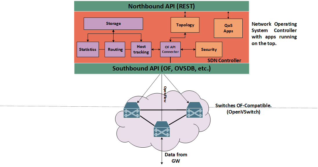
Figure 1. High level architecture of an SDN network and controller.
Recipe ingredients
Main ingredients to create and test this dish are the following:
- Hardware:
- Computer with Ubuntu 14.04 or greater.
- If desired, you can exchange the virtual switch for a physical one (real), we have tested this deployment with Zodiac FX.
- Software:
- A virtual switch, in this case we will use OpenVSwitch.
- SDN controller, in this case we will use the one provided by INTER-IoT (Ryu-Based).
- An SDN application, in this case this one is running at the top of the controller (already included).
- A virtual environment to test the connectivity, we can use Mininet to set up a virtual environment o configure the network to use Docker containers.
- Measurement tools to obtain results of the set-up, in this case iperf and cbench.
Prerequisites
First of all we must have installed in our environment the software prerequisites in order to run smoothly all components to set-up the network. These prerequisites can be found at:
https://inter-iot.readthedocs.io/projects/n2n/en/latest/sdn-solution/user-guide/
In summary, these requisites include:
- Python 2.7
- Pip
- (Optional) Install Java 1.8 JRE or JDK in case we want to run the INTER-IoT gateways on the nodes.
Concretely, there are dependencies for building the Python packages that also is recommended to have installed:
- gcc
- python-dev
- libffi-dev
- libssl-dev
- libxml2-dev
- libxslt1-dev
- zlib1g-dev
Moreover, we must install a switch compatible with the OpenFlow version that we will use in the network. In this case, the OpenFlow version used is 1.3, and the switch chosen has been OpenVSwitch. Information for the installation and configuration of OpenVSwitch can be found in the following link:
http://docs.openvswitch.org/en/latest/intro/install/
Software installation and switch configuration
Installation and configuration of OpenVSwitch
Once software is installed in our computer we will proceed with the set up. To install OpenVSwitch once the code is downloaded execute the following steps:
- Run GNU
makein the build directory:
$ make
- Run
makeinstall to install the executables and man pages into the running system, by default under/usr/local:
$ make install
-
If you built kernel modules please refer to the OpenVSwitch documentation
-
On Unix-alike systems, such our, starting the Open vSwitch suite of daemons is a simple process. Open vSwitch includes a shell script, and helpers, called
ovs-ctlwhich automates much of the tasks for starting and stoppingovsdb-server, andovs-vswitchd. After installation, the daemons can be started by using theovs-ctlutility. This will take care to setup initial conditions, and start the daemons in the correct order. Theovs-ctlutility is located in$(pkgdatadir)/scripts, and defaults to/usr/local/share/openvswitch/scripts. An example after install might be:
$ export PATH=$PATH:/usr/local/share/openvswitch/scripts
$ ovs-ctl start
Additionally, the ovs-ctl script allows starting and stopping the daemons individually using specific options. To start just the ovsdb-server execute: ovs-ctl --no-ovsdb-server start, and for start and stop just the ovs-vswitchd execute: ovs-ctl --no-ovs-vswitchd start
However, instead of using the automated script to start Open vSwitch, you may wish to manually start the various daemons. Then, before starting ovs-vswitchd itself, you need to start its configuration database; ovsdb-server. Before ovsdb-server itself can be started, configure a database as follows:
$ mkdir -p /usr/local/etc/openvswitch
$ ovsdb-tool create /usr/local/etc/openvswitch/conf.db \
    vswitchd/vswitch.ovsschema
This will create the database with the OVS schema used by the daemon. Later, we must configure ovsdb-server to use the database that we just create in order to listen on a Unix domain socket, to connect to any managers specified in the database itself and to use the secure SSL configuration. For that we will type the following commands:
$ mkdir -p /usr/local/var/run/openvswitch
$ ovsdb-server --remote=punix:/usr/local/var/run/openvswitch/db.sock \
    --remote=db:Open_vSwitch,Open_vSwitch,manager_options \
    --private-key=db:Open_vSwitch,SSL,private_key \
    --certificate=db:Open_vSwitch,SSL,certificate \
    --bootstrap-ca-cert=db:Open_vSwitch,SSL,ca_cert \
    --pidfile --detach --log-file
- After this, we must initialize the database using the command
ovs-vsctl. This will be only necessary the first time you create and configure the database as above, however running it at any time is harmless:
$ ovs-vsctl --no-wait init
- Finally, we can start the main daemon of OpenVSwitch, telling it to connect to the same Unix domain socket:
$ ovs-vswitchd --pidfile --detach --log-file
- To start/stop/restart OpenVSwitch as a service on the fly, once the database is created and configured we can also use:
$ /etc/init.d/openvswitch-switch start/stop/restart
- To test the installation and configuration type:
$ ovs-vsctl show
Installation of controller
Later on, we must install the controller. Once cloned from the repository (https://github.com/INTER-IoT/n2n-ryu) proceed with the installation as follows:
$ cd ryu
$ pip install .
Creation of topology
To create the network topology we will use Mininet, that will configure the network interfaces and will create the bridges within OpenVSwitch in order to connect with the virtual host. For that we use the command:
$ sudo mn --topo single,3 --mac --switch ovsk --controller
remote
This command will create a simple start topology of three virtual hosts connected to OpenVSwitch. Modifying this command we can create different topologies as tree, ring or even a custom one from a file descriptor. Also, this command indicates that the switch will be ovsk and the controller will be remote, that is, not the one provided by default.
Typing the command:
$ sudo ovs-ofctl show s1
We can check the network interfaces configuration within the virtual switch as it can be observed in the following figure.
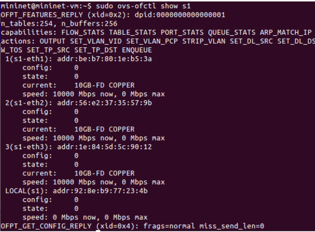
Figure 2. Configuration of the virtual switch.
Running and collecting results
Next step is to run the controller together with the application to manage the traffic within the network, we do so using the command:
$ cd ryu
$ ryu-manager --observe-links ryu/app/gui_topology/gui_topology.py ryu/app/InterIoT_simple_switch_13.py
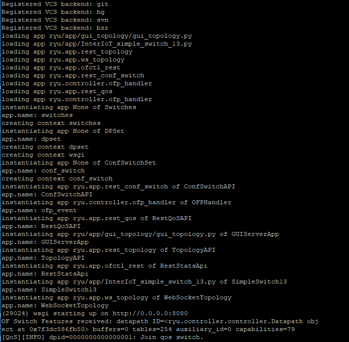
Figure 3. Logs from the controller at init.
This will run an application that performs operations of a L2 switch using OpenFlow version 1.3 and, together with the switching mechanism, provides some QoS features as the possibility to set queues, meters and rules. Moreover, it starts the GUI application to visualize and interact with the network.
To take a look to the final topology setup we can observe in the figure below the components and its connections; three virtual hosts connected to the virtual switch and this one being managed by the controller.
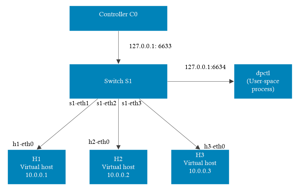
Figure 4. Network topology of the set up.
If you have been successful, the controller should have been automatically installed the corresponding flow entries within the switch to allow communication between host. We can check it making a dump of the tables of the switch with:
$ ovs-ofctl dump-flows s1
In order to verify its proper function and evaluate this set up you can perform a series of test:
- Using of iperf as a command utility to check network speed of a connection between two nodes.
- Using of cbench as a benchmark tool to test the controller latency and throughput within the creation of flows through the generation of Packet-in messages.
Examples of this utilities can be seen in figures:
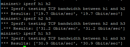
Figure 5. Bandwidth test with iperf.
In this case we observe within the network the results of an iperf example that check the bandwidth between virtual hosts. In the following figures we observe the that by using the tool cbench we can obtain more information regarding the deployment. In concrete, we can test the capacity in terms of latency and throughput of the controller used for this deployment.
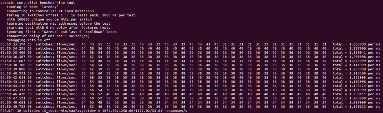
Figure 6. latency test with cbench.
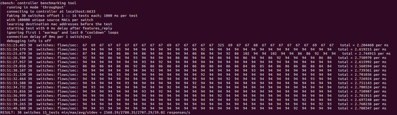
Figure 7. Throughput test with cbench
Wrap up
Following this recipe we have obtained a virtual SDN network composed by virtual hosts and switch, and the SDN controller provided by Inter-IoT. Hereinafter, we can perform customize the network in order to perform testing or to be applied to the different use cases that Inter-IoT provides. This is a simple but powerful example on how is possible to create a whole infrastructure of nodes interconnected within a single serve,r and having the ability of monitor and manage the whole network from a single point.