INTER-LAYER - Device to Device (D2D): Getting Started with a Physical and Virtual basic demo setup with Arduino
(Getting Ready) Demo description
In this demo we will setup a basic introductory scenario in which we will setup the physical gateway inside a Raspberry Pi and connect it to a virtual gateway, that is running in a Windows computer. Of course, in a real world scenario you could use an industrial embedded system for the physical gateway and the virtual gateway could be deployed in a cloud provider.
We will connect some LEDs and a pushbutton in the Arduino as devices for this demo, as well as one simulated sensor. Afterwards we will define simple rules in the virtual gateway to generate some automated actions.
In the following image we can see the demo scenario setup:
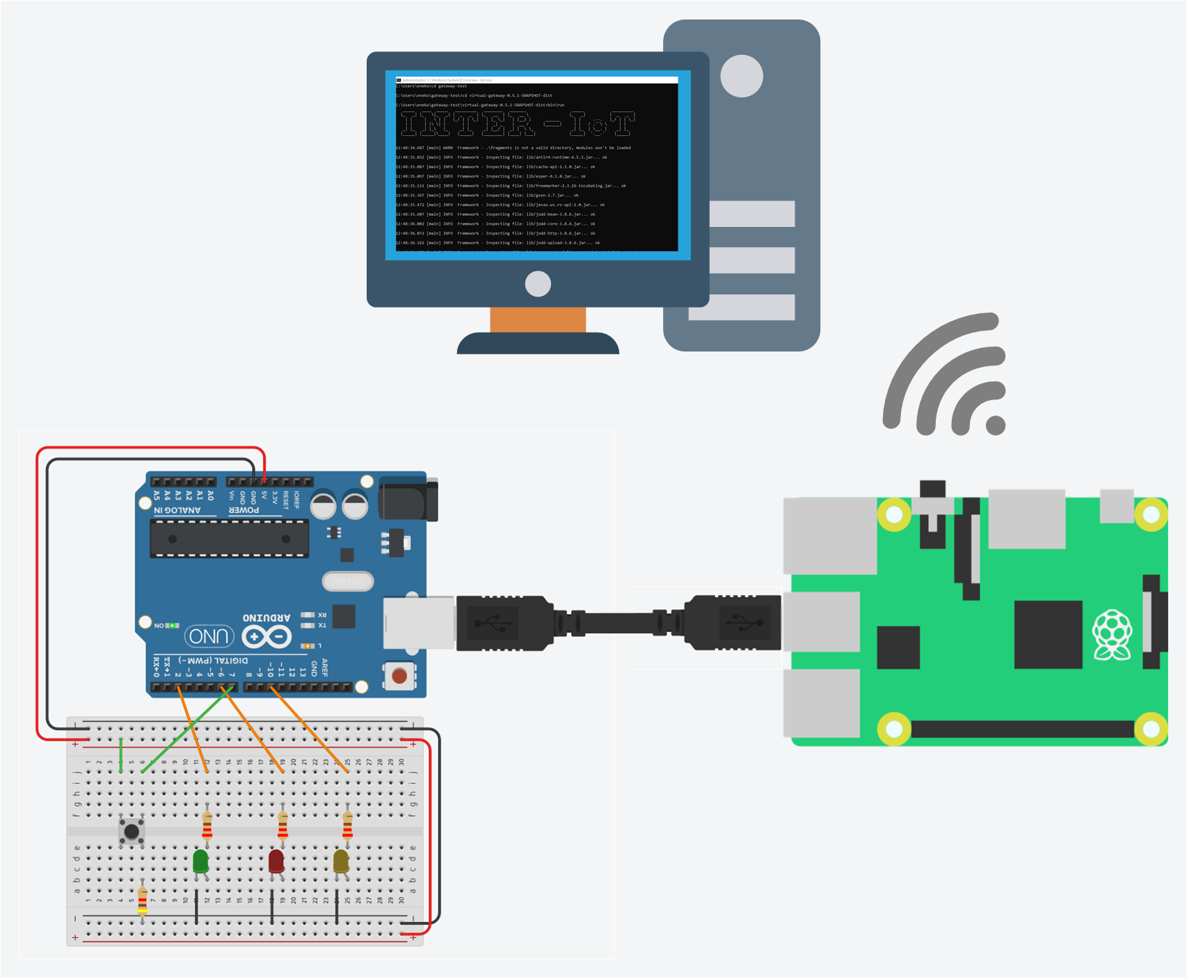
Figure 1. Demo setup overview.
Recipe ingredients
- Hardware:
- Raspberry PI 3B+ (recommended, 1B+/2B/3B/3A+ also supported).
- Arduino UNO (recommended, any version supporting Firmata 2 and Serial COM would also work).
- Breadboard, LEDs, Jumpwires, Pushbutton, Resistors (220Ω or more, depending on LED power).
- Computer.
- USB A Male to B Male cable.
- Software:
- Raspbian for the Raspberry (or any OS that supports Java 1.8+).
- Any OS in the computer that supports Java 1.8+.
- Firmata 2 flashed in the Arduino UNO.
Prerequisites
- Install Java 1.8 JRE or JDK on the computer.
- Install Firmata 2 in the Arduino.
- Install Java 1.8 JRE on the Raspberry PI:
sudo apt-get update && sudo apt-get install -y oracle-java8-jdk. - Raspberry PI should be able to reach the computer over the network.
(How to Do it) Hardware & Software installation and module configuration
Arduino Wiring
- Follow this schematic to setup the Arduino Wiring. The resistors used are 220Ω for the LEDs and 4.1kΩ for the pushbutton:
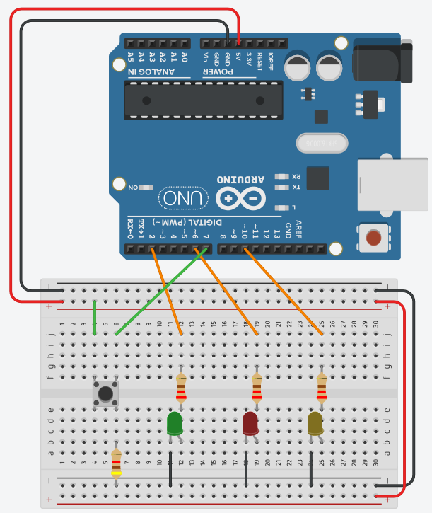
Figure 2. Arduino wiring schematic.
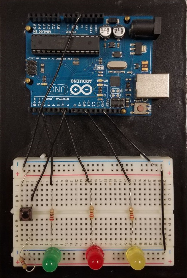
Figure 3. Arduino wiring example.
Raspberry PI Hardware Setup
-
Connect USB A Male to Arduino and USB B Male to the Raspberry PI.
-
Connect also the Raspberry PI to a network where your computer is reachable.
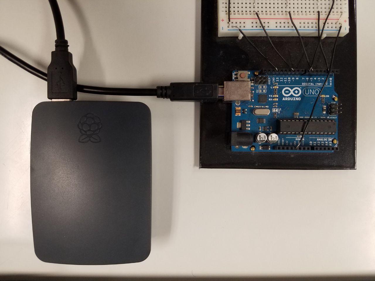
Figure 4. Arduino connected to the Raspberry PI.
Installing and configuring the Physical Gateway
-
Run the following commands in the Raspberry PI to install the current (0.5.1) version of the Physical Gateway:
pi$ mkdir physical-gateway

pi$ wget https://github.com/INTER-IoT/gateway/releases/download/0.5.1-SNAPSHOT/physical-gateway-0.5.1-SNAPSHOT-dist.zip

pi$ unzip physical-gateway-0.5.1-SNAPSHOT-dist.zip -d physical-gateway
Refer to the main documentation Installation section for more information.
-
Install the Arduino, Simulator and Console extension for the physical gateway:
pi$ wget https://github.com/INTER-IoT/gateway-extensions-physical/releases/download/0.5.1-SNAPSHOT/device-controller.arduino-uno-0.5.1-SNAPSHOT-dist.zip

pi$ wget https://github.com/INTER-IoT/gateway-extensions-physical/releases/download/0.5.1-SNAPSHOT/device-controller.simulator-0.5.1-SNAPSHOT-dist.zip

pi$ wget https://github.com/INTER-IoT/gateway-extensions-common/releases/download/0.5.1-SNAPSHOT/console-0.5.1-SNAPSHOT-dist.zip

pi$ cd physical-gateway

physical-gateway$ bin/run --install ../device-controller.arduino-uno-0.5.1-SNAPSHOT-dist.zip

physical-gateway$ bin/run --install ../console-0.5.1-SNAPSHOT-dist.zip
Refer to the main documentation Installing extensions section for more information.
-
Copy the example device definitions to the
devicesfolder:pi$ cp device-examples/arduino.json devices pi$ cp device-examples/temp.sim.json devices -
Create a new file under the
conf.d/directory named10.demo.propertieswith the following content:eu.interiot.gateway.core.common.connector.host: <computer ip or address name>With the computer ip or address name reachable from the Raspberry PI (without the <>). Other configuration options are documented in the main documentation Basic Configuration and Physical Configuration sections.
-
Find in which device file has been the Arduino USB connected in the Raspberry. For that, you can run
dmesgin your Raspberry and disconnect/connect the Arduino USB. You have to find in which/dev/ttyXXXXhas been connected, in the following image you can see that in this case it has been connected in/dev/ttyACM0: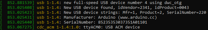
Figure 5. dmesg command output.
-
Edit the file
devices/arduino.jsonto match your demo setup (special attention to theconfig.portvalue), if you followed the schematic it should look like this:{ "id": "AAAAAA", "type": "arduino", "controller": "arduino-uno", "description": "Arduino Firmata-2.0 configuration file for LINUX", "config": { "port": "/dev/ttyACM0" }, "device_io": [ { "type":"actuator", "attr_name":"red-led", "attr_type":"boolean", "config": { "pin": 6 } }, { "type": "actuator", "attr_name": "green-led", "attr_type": "boolean", "config": { "pin": 2 } }, { "type": "actuator", "attr_name": "yellow-led", "attr_type": "boolean", "config": { "pin": 10 } }, { "type": "sensor", "attr_name": "switch", "attr_type": "boolean", "config": { "pin": 7 } } ] } -
Edit the file
devices/temp.sim.jsonto give a known ID instead of a random one:{ "id": "AAABBB", "type": "simulated", ... -
Each extension has it's own documentation for the device definitions, refer to their repositories for more documentation.
Installing and configuring the Virtual Gateway
-
Download an unzip the Virtual Gateway in the computer
Refer to the main documentation Installation section for more information.
-
Download the API extension and Rules Engine extension
-
Install the extensions running the following commands:
virtual-gateway> bin\run.cmd --install ..\api-engine-0.5.1-SNAPSHOT-dist.zip

virtual-gateway> bin\run.cmd --install ..\rules-engine-0.5.1-SNAPSHOT-dist.zip
Refer to the main documentation Installing extensions section for more information.
-
In this case we will leave the default ports for the API and WebSocket. Refer to the main documentation Basic Configuration and Virtual Configuration sections for more options.
(How it Works) Running and collecting results
-
To start the Virtual Gateway, run the following command in the computer:
virtual-gateway> bin\run.cmd -
To start the Physical Gateway, run the following command in the Raspberry PI:
sudo bin/run -
Wait until the physical and virtual gateway are connected, it shouldn't take long. In the main documentation, you can find more documentation on running the gateway.
-
You will have a command line interface in your physical gateway where you can input commands. Type the following commands to show the devices and start them:
gateway> device list
gateway> device connect AAAAAA
gateway> device connect AAABBB
If everything went well, you should see something like this:
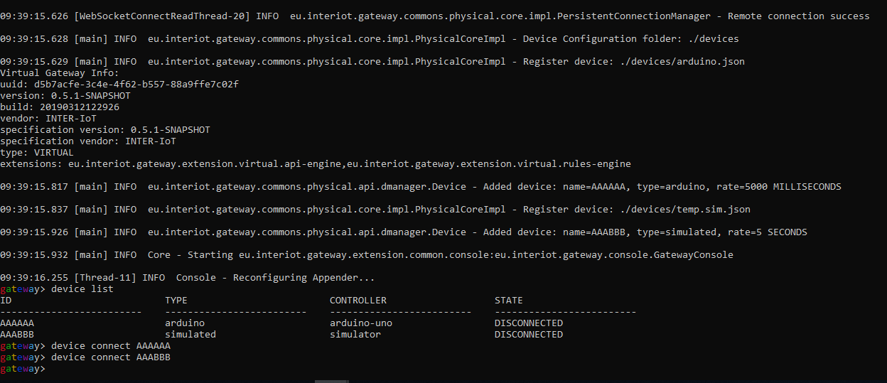
Figure 6. Physical gateway command line.
-
At this point, you should be able to play with the API (by default in http://localhost:8080/swagger/index.html to change the LED status through the Virtual Gateway. For example, in the following image you can see how to change the red led value to high:
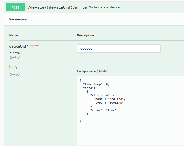
Figure 7. Write device REST API call.
-
Finally, we will add some rules to change the red led status depending on the temperature value that the device simulator is sending every 5 seconds. In this case, as the temperature value goes from -50 to +50, we will setup the breakpoint at 0 so there is a 50% chance on setting it on or off:
- Add a statement through the REST API
/extensions/rules/statements/addcall with the following content int the body and keep the returned id:{ "name": "st01", "description": "Temperature greater or equal than 0", "statement": "select * from Measurement where data.attribute.name = 'temperature' and cast(data.value, double) >= 0" }
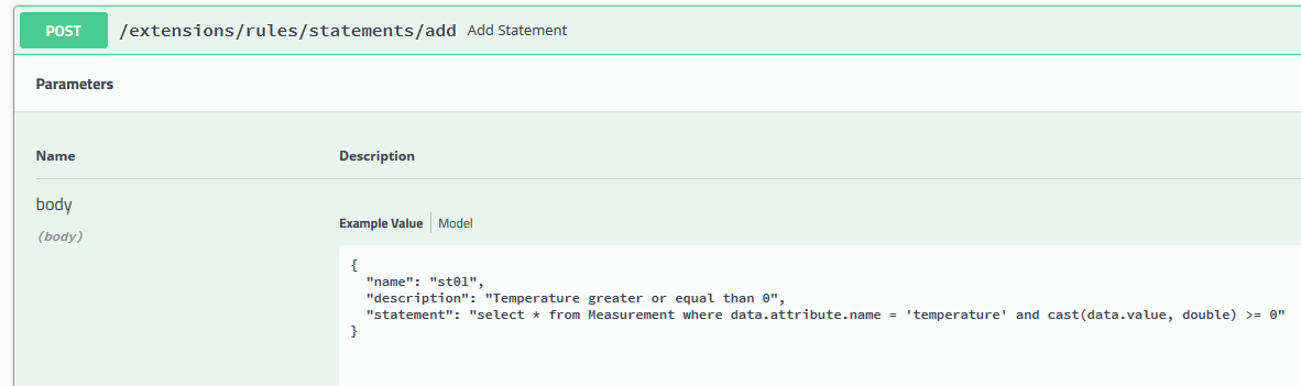
Figure 8. Add statement REST API call.
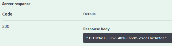
Figure 9. Add statement REST API call returned id value
-
Add another statement but this time for temperatures lower than 0. Keep the returned id:
{ "name": "st02", "description": "Temperature lower than 0", "statement": "select * from Measurement where data.attribute.name = 'temperature' and cast(data.value, double) < 0" } -
Add an execution to power on the red led through the REST API call
/extensions/rules/executions/add. Keep the returned id:{ "name": "ex01", "description": "Red led arduino AAAAAA to ON", "execution": "var action = new Action(); action.addData(new ActionData('red-led', AttributeType.BOOLEAN, true)); context.sendAction('AAAAAA', action);" } -
Add another execution but this time to power off the red led. Keep the returned id:
{ "name": "ex02", "description": "Red led arduino AAAAAA to OFF", "execution": "var action = new Action(); action.addData(new ActionData('red-led', AttributeType.BOOLEAN, false)); context.sendAction('AAAAAA', action);" } -
The IDs are randomly generated, in our case we got the following ids:
name description id st01 Temperature greater or equal than 0 19f9f6e1-5957-4b26-a59f-c2cd16c3a3ca st02 Temperature lower than 0 c8d646c9-ea5e-48ce-9036-318a36cd6852 ex01 Red led arduino AAAAAA to ON 96dc45de-7d48-4ce6-bbf6-6c5342d8e31c ex02 Red led arduino AAAAAA to OFF 39d4581c-a302-4ca1-b36b-eb0ac7c8ef36 -
Finally, we will wire things up in rules that given a statement fire the executions. For that we will make two more REST API calls to
/extensions/rules/rules/addwith the following bodies:{ "name": "rule01", "description": "when temp > 0 then red-led = true", "statementId": "19f9f6e1-5957-4b26-a59f-c2cd16c3a3ca", "executionId": "96dc45de-7d48-4ce6-bbf6-6c5342d8e31c" }And:
{ "name": "rule02", "description": "when temp < 0 then red-led = false", "statementId": "c8d646c9-ea5e-48ce-9036-318a36cd6852", "executionId": "39d4581c-a302-4ca1-b36b-eb0ac7c8ef36" } -
Once the rules are added, we will see that the red led will start randomly blinking depending on the temperature value that the simulator sends.
- Add a statement through the REST API
Wrapping things up
This is a very basic setup to test the physical and virtual gateway. As an interesting follow-up, the reader could also try to incorporate a rule that depending if the pushbutton is pressed the green-led status changes from ON to OFF.
Refer to the More Resources section in the main documentation to find links to other useful resources for users and developers of the INTER-IoT Gateway.